
Install Video
Diagrams
A-Harness Integrated with KTJO's Full Kit

B-Harness

B-Harness Routing
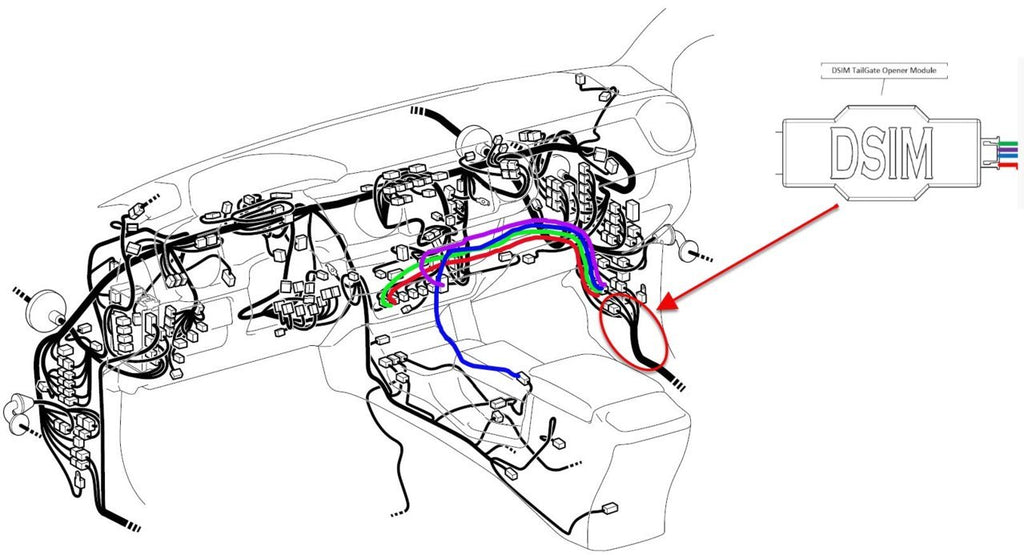
Step 1: With T-Harness UNPLUGGED connect A-Harness to KTJO's T-Harness and Integrated Harness (for the actuator) following the diagram in post #2.
Step 2: Hook up TailGate Opener module while still UNPLUGGED from the truck. The white connector can only be connected fully one way. If you were to hook it up upside down while still plugged in it is possible to damage the board inside. (The cable will be shipped connected in the correct orientation for reference).
Step 3: As far as the Module is concerned you are done. The rest is KTJOs Kit for installation of the T-Harness, Integrated (Actuator) Harness, Bracket, and actuator. You can find her instructions HERE.
Step 4: Check that your Radio Settings match the below picture. Else the module will likely work with 4x Unlock instead of 3x.
Step 5: TEST!
Installation of this complete kit is very straightforward however if any issues arise during installation of the TailGate Opener Module please refer to the Trouble-Shooting information below. If you try the steps below and still have issues please contact me at dsim.solutions@gmail.com OR shoot me a PM.
Enable/Disable Sequence
- Hold Push Button down for 10 Seconds. If enabled it will disabled, if disabled it will enable the module.
Trouble-Shooting
Step 1: Pop open the enclosure. Check and make sure there is a red led on indicating that the arduino board is on.
LED is ON.
LED NOT ON
Step 2: Unplug A-Harness. Led should turn off.
LED should be off in ALL Scenarios.
Step 3: Plug it back in to reset the module. Led should be on.
Red LED is ON
LED NOT ON
Step 4: Press unlock 4 times. There should be another led on the arduino that should blink with each unlock press (TX LED). After the TX blinks 3 times you should audibly hear the relay on the board "Click".
TX LED only Blinked 3 Times on 4 unlock presses.
TX LED Blinked 4 Times on 4 unlock presses.
GOOD. Your Radio Settings are configured for 3x Tailgate Open
The TX LED did not blink at all
The TX LED blinked, but the Relay DID NOT CLICK
The TX LED blinked, the Relay Clicked, but the actuator did not move.
The TX LED blinked, the Relay Clicked, Actuator Moved, but TailGate did not drop